Join Our Lunch & Learn: How Agentic AI Will Transform Industrial Operations | Register Now →
.svg)
September 10, 2026
6 Mins
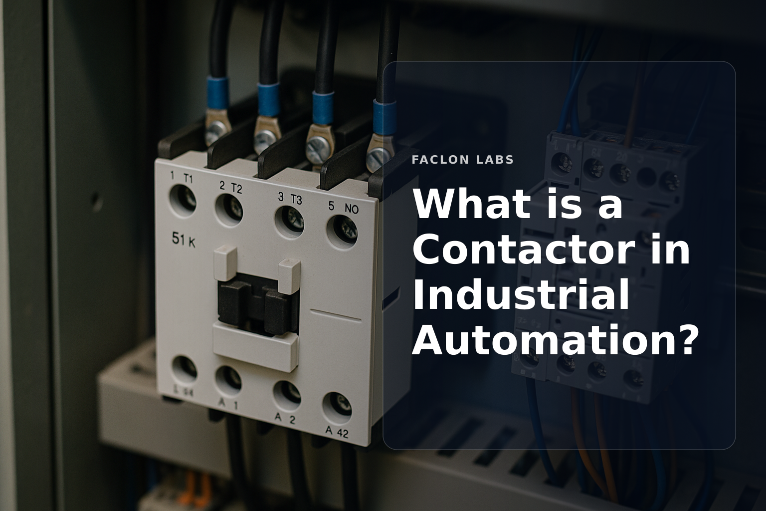
Industrial automation relies on precise control of electrical power to operate machinery and processes efficiently and safely. Contactors are fundamental components in these systems, enabling automated switching of high-voltage and high-current equipment. Understanding what a contactor is and how it functions is essential for plant operations leaders and engineers who manage industrial controls.
This article explains the role of contactors in industrial automation, how they operate, their key applications, and how they differ from similar devices like relays. The goal is to provide a clear, technical, yet accessible overview that helps readers grasp why contactors are indispensable in modern industrial settings.
A contactor is a specialized type of electrically operated switch designed to control the flow of electrical power in industrial circuits. Unlike general-purpose switches, contactors handle much higher current and voltage levels, making them suitable for heavy-duty applications.
The main role of a contactor is to open or close power circuits, allowing or interrupting electricity flow to devices like motors, heaters, and lighting systems. This switching is done remotely and automatically, often controlled by programmable logic controllers (PLCs) or other automation systems.
While contactors and relays both use electromagnetic principles to switch circuits, contactors are specifically built for high power loads and frequent switching. They have robust contacts and enclosures to withstand electrical and mechanical stresses that would damage standard relays.
At the core of a contactor's operation is an electromagnetic coil. When a control voltage energizes this coil, it generates a magnetic field that moves internal components to either close or open the power contacts.
A contactor consists of:
The coil receives a control signal, typically from a PLC or pushbutton, which magnetizes the coil. This magnetic force pulls the movable contacts toward the fixed contacts, closing the circuit and allowing current to flow.
Contactors commonly have:
Most industrial contactors primarily use NO contacts to control power circuits.
Contactors enable safe switching of heavy electrical loads such as motors and heaters without exposing operators to live circuits. Their design supports the high current and voltage demands typical in industrial environments.
By using a low-voltage control signal to operate the coil, contactors provide galvanic isolation between the control system and the power circuit. This separation protects sensitive control electronics from electrical faults.
Contactors can be integrated into automated control schemes, allowing PLCs and other controllers to start or stop equipment remotely and reliably, which is critical for process automation and safety interlocks.
Although contactors alone do not provide overload protection, they are often paired with thermal overload relays or circuit breakers that protect motors and other loads from damage due to excessive current.
Contactors are versatile and widely used across industrial sectors. Common applications include:
| Application | Load Type | Purpose |
|---|---|---|
| Motor control | Inductive loads | Start/stop motors safely |
| HVAC systems | Motors, heaters | Control climate equipment |
| Industrial lighting | Resistive/inductive | Manage large lighting banks |
| Capacitor banks | Capacitive loads | Power factor correction |
| Heating elements | Resistive loads | Control temperature devices |
Contactors are designed for either alternating current (AC) or direct current (DC) loads. AC contactors typically handle inductive loads like motors, while DC contactors are used in applications such as battery systems or DC motors, requiring different coil and contact designs.
Contactors come in various pole configurations:
Selecting a contactor involves matching its current and voltage ratings to the application’s requirements, considering the type of load and the duty cycle. Ratings are often specified per utilization category, reflecting the load type and switching frequency.
Environmental factors like temperature, humidity, and exposure to dust or chemicals influence contactor selection. Duty cycle—how often and how long the contactor switches—also affects the choice to ensure reliability and longevity.
Some applications require specialized contactors such as:
| Type | Typical Use | Key Feature |
|---|---|---|
| AC contactor | Motors, lighting | Designed for AC loads |
| DC contactor | Battery systems, DC motors | Handles DC arcs effectively |
| Vacuum contactor | High voltage industrial equipment | Arc-free switching |
| Definite purpose contactor | HVAC, refrigeration | Tailored for specific loads |
The main difference between contactors and relays lies in their power handling capability. Contactors are engineered for high current and voltage switching, while relays generally control lower power circuits.
Relays are often used in control panels and signal circuits where the current is low, such as switching control signals or indicator lights.
Contactors switch main power circuits feeding motors, heaters, and lighting loads, where the electrical demands are significantly higher.
Both devices operate on the principle of an electromagnetic coil actuating contacts, but contactors have more robust construction to handle industrial power loads.
Contactors form a critical link between control systems and industrial equipment, ensuring reliable and safe power management. For plant operations leaders exploring automation upgrades or maintenance strategies, understanding contactors is fundamental. To deepen your knowledge of industrial control components and their integration with IIoT platforms, explore our posts on What is a Frequency Drive and How Does It Work?, Implementing Industrial Automation Solutions for Smart Factories, and Designing Robust Industrial AI Platform Architectures.
The main function of a contactor is to repeatedly make and break an electrical power circuit, safely controlling high-voltage and high-current loads like industrial motors, heating elements, and lighting from a low-voltage control signal.
While both are electromechanical switches, a contactor is designed for switching high-power circuits (typically 9A and above) and heavy loads, whereas a relay is generally used for switching lower power control circuits and signals.
Yes, contactors are available for both AC (alternating current) and DC (direct current) applications. The design of the coil and arc suppression mechanisms differs between AC and DC contactors to handle their respective current characteristics effectively.
A contactor typically consists of a coil (electromagnet), fixed and movable contacts, an arc chute (to extinguish arcs during switching), and an enclosure. Auxiliary contacts may also be included for signaling or interlocking purposes.